Welcom Changzhou Senmet Microelectronics Co., Ltd.!
Industry knowledge
time:2021-04-28 view:1163
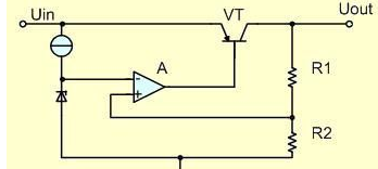
The basic circuit of a low-dropout linear regulator (LDO) is shown in Figure 1-1. The circuit is composed of a series regulator VT, sampling resistors R1 and R2, and a comparison amplifier A.
The sampling voltage is applied to the non-inverting input terminal of the comparator A and compared with the reference voltage Uref applied to the inverting input terminal. After the difference between the two is amplified by the amplifier A, the voltage drop of the series regulator is controlled to stabilize the output voltage. When the output voltage Uout decreases, the difference between the reference voltage and the sampling voltage increases, the drive current output by the comparison amplifier increases, and the voltage drop of the series regulator tube decreases, thereby increasing the output voltage. On the contrary, if the output voltage Uout exceeds the required setting value, the front drive current output by the comparison amplifier decreases, thereby reducing the output voltage. During the power supply process, the output voltage correction is performed continuously, and the adjustment time is only limited by the reaction speed of the comparator amplifier and the output transistor loop. It should be noted that the actual linear regulator should also have many other functions, such as load short-circuit protection, over-voltage shutdown, over-temperature shutdown, reverse connection protection, etc., and the series regulator can also use MOSFET.
two. The main parameters of the low dropout linear regulator
1. Output voltage (OutputVoltage)
The output voltage is the most important parameter of the low dropout linear regulator, and it is also the first parameter that the electronic equipment designer should consider when choosing the regulator. There are two types of low dropout linear regulators: fixed output voltage and adjustable output voltage. The fixed output voltage regulator is more convenient to use, and because the output voltage is precisely adjusted by the manufacturer, the regulator has a high accuracy. However, the set output voltage values are all common voltage values, which cannot meet all application requirements, but changes in the values of external components will affect the stability and accuracy.

2. Maximum output current (MaximumOutputCurrent)
The power of the electrical equipment is different, and the maximum current that the voltage stabilizer is required to output is also different. Generally, the higher the output current, the higher the cost of the regulator. In order to reduce costs, in a power supply system composed of multiple voltage stabilizers, an appropriate voltage stabilizer should be selected according to the current value required by each part.

3. Input and output voltage difference (DropoutVoltage)
The input and output voltage difference is the most important parameter of the low dropout linear regulator. Under the condition that the output voltage is stable, the lower the voltage drop, the better the performance of the linear regulator. For example, a 5.0V low dropout linear regulator, as long as the input voltage is 5.5V, the output voltage can be stabilized at 5.0V.

4. Ground current (GroundPinCurrent)
Grounding circuit IGND refers to the voltage regulator operating current provided by the input power supply when the output current of the series regulator tube is zero. This current is sometimes called quiescent current, but when a PNP transistor is used as a series pass element, this customary name is incorrect. The ground current of the ideal low-dropout regulator is usually very small.

5. Load Regulation (LoadRegulation)
The load regulation rate can be defined by Figure 2-1 and Equation 2-1. The smaller the LDO load regulation rate, the stronger the LDO's ability to suppress load interference.
(2-1) where △Vload-load regulation rate Imax-LDO maximum output current Vt-when output current is Imax, LDO output voltage Vo-when output current is 0.1mA, LDO output voltage △V-load current respectively The difference between the output voltage at 0.1mA and Imax

6. Linear adjustment rate (LineRegulation)
The linear adjustment rate can be defined by Figure 2-2 and Equation 2-2. The smaller the linear adjustment rate of the LDO is, the less the input voltage change affects the output voltage, and the better the performance of the LDO.
(2-2) where △Vline-LDO linear adjustment rate Vo-LDO nominal output voltage Vmax-LDO maximum input voltage△V-LDO input Vo to Vmax’ difference between the maximum and minimum output voltage

7. Power Supply Rejection Ratio (PSSR)
The input source of LDO often has many interference signals. PSRR reflects the LDO's ability to suppress these interference signals.

Related display
Contact Us

Tel:+86-0519-88669981
Email:hyper@tm-micro.com
Provide you with high-performance
analog and mixed-signal integrated circuit (IC) design

Wechat QR code
Application field
Contact Us